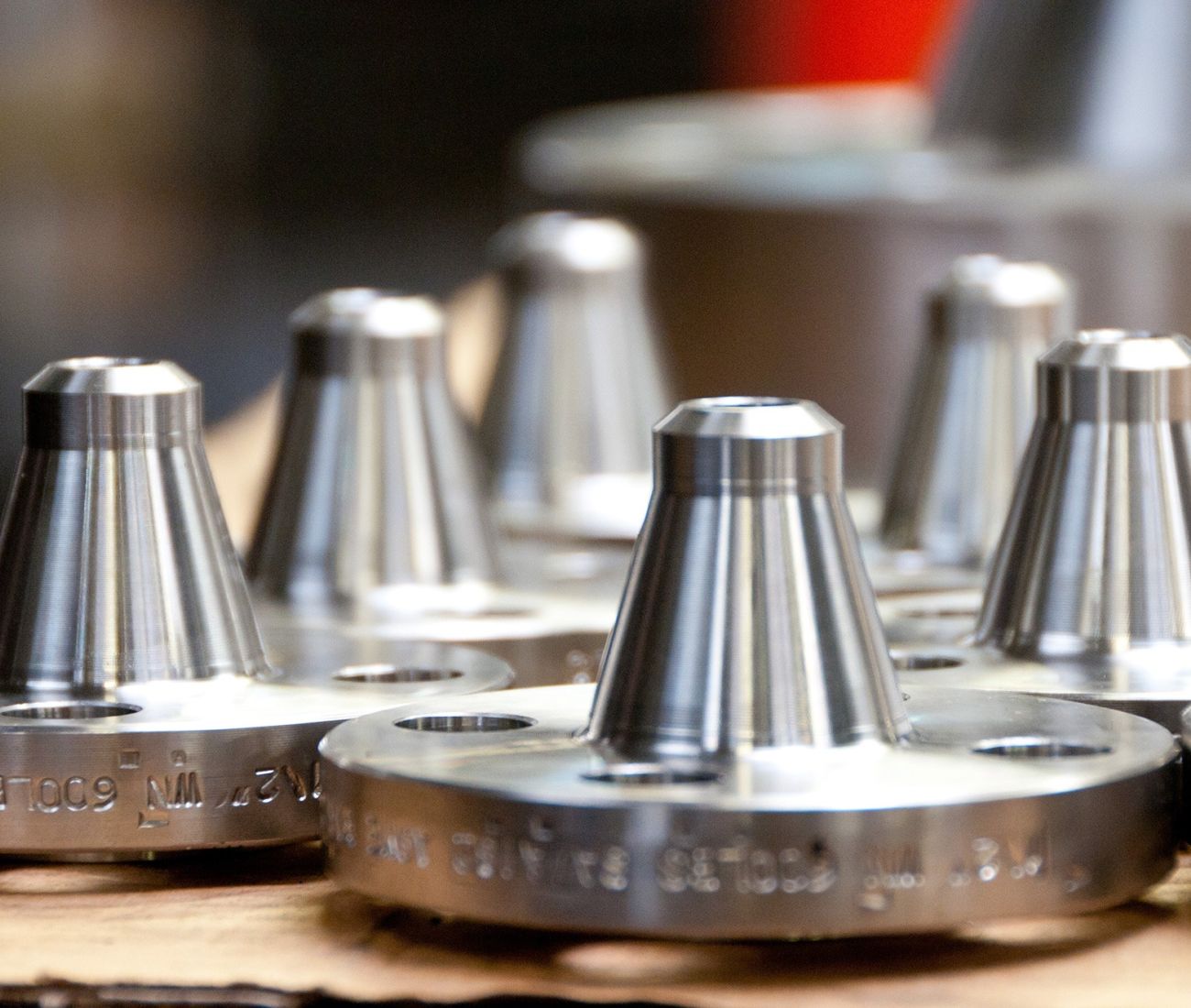
FLANGES

Alexander Comley LTD holds OEM & end user approvals across Nuclear, Power, Process, Oil, Gas, Marine and Defence sectors. A market leading engineering company with a First Time Right approach to manufacturing complex, critical, pressure retaining parts.
A manufacturer of flanges to international standards including API 6A, API 590 Spectacle flanges, B16.48 Paddle Blank, Paddle Spacer, B16.5, B16.36 Orifice Flanges, BS10 and EN1092-1 Weld Neck, Slip-On and Blind PN Flanges.
A stockist of non-EU 316/L + 304/L stainless steel flanges up to 24” NB, 2,500 lbs (finished/semi-finished) to B16.5, B16.36, BS10 & EN1092-1.
-
Stainless Steel Flange stock | B16.5, EN1092-1, B16.36 | up to 24” NB, 2,500 lbs.
-
Examples: Large flanges | B16.47 (A/B), BS 3292, B16.5.
-
Examples: Orifice flanges | B16.36.
-
Examples: API Flanges | API 6A, API 590.
-
Examples: Line blank flanges: paddle blank, paddle spacer | B16.48.
-
Max capacity: 2,000 mm dia OD.
-
Materials: Stainless Steel, Nickel Alloys, Carbon Steel, Copper, Duplex, Super Duplex, Cupronickel, Nickel Alloys, Titanium and many more.
-
Destructive testing: UKAS laboratories | tensile, charpy, hardness.
-
Non-destructive testing: UKAS laboratories | UT, DPI, MPI, PMI.
-
Certification: EN10204 3.1 | EN 10204 3.2.
We manufacture Special Flanges, Tubesheets, Filter Plates, Large Rings, Machined Components & Pipe Fittings.
We stock stainless steel flanges as B16.5, EN1092-1, B16.36 up to 24” NB, 2,500 lbs.
We source from supply chain, Plate, Fasteners, Gaskets & Pipe.
FLANGES
Alexander Comley LTD holds OEM & end user approvals across Nuclear, Power, Process, Oil, Gas, Marine and Defence sectors. A market leading engineering company with a First Time Right approach to manufacturing complex, critical, pressure retaining parts.
A manufacturer of flanges to international standards including API 6A, API 590 Spectacle flanges, B16.48 Paddle Blank, Paddle Spacer, B16.5, B16.36 Orifice Flanges, BS10 and EN1092-1 Weld Neck, Slip-On and Blind PN Flanges.
A stockist of non-EU 316/L + 304/L stainless steel flanges up to 24” NB, 2,500 lbs (finished/semi-finished) to B16.5, B16.36, BS10 & EN1092-1.

-
Stainless Steel Flange stock | B16.5, EN1092-1, B16.36 | up to 24” NB, 2,500 lbs.
-
Examples: Large flanges | B16.47 (A/B), BS 3292, B16.5.
-
Examples: Orifice flanges | B16.36.
-
Examples: API Flanges | API 6A, API 590.
-
Examples: Line blank flanges: paddle blank, paddle spacer | B16.48.
-
Max capacity: 2,000 mm dia OD.
-
Materials: Stainless Steel, Nickel Alloys, Carbon Steel, Copper, Duplex, Super Duplex, Cupronickel, Nickel Alloys, Titanium and many more.
-
Destructive testing: UKAS laboratories | tensile, charpy, hardness.
-
Non-destructive testing: UKAS laboratories | UT, DPI, MPI, PMI.
-
Certification: EN10204 3.1 | EN 10204 3.2.
We manufacture Special Flanges, Tubesheets, Filter Plates, Large Rings, Machined Components & Pipe Fittings.
We stock stainless steel flanges as B16.5, EN1092-1, B16.36 up to 24” NB, 2,500 lbs.
We source from supply chain, Plate, Fasteners, Gaskets & Pipe.
HAVE ANY QUESTIONS?
Click to send an email or call us. The team has decades of experience. 100 years of proud customer history can’t be wrong.
What we do
MANUFACTURER: special flanges (custom drawings), large flanges (international standards), up to 2,000 mm diameter.
STOCKIST: non-EU 316/L + 304/L stainless steel flanges up to 24” NB, 2,500 lbs (finished/semi-finished) to B16.5, B16.36, BS10 & EN1092-1.
PROJECT MANAGEMENT/PROCUREMENT SERVICES: from decades of managing projects, applying skill, knowledge and experience, as needed, we manage the entire supply chain across material(s) requisition, manufacturing, testing, certification and delivery to you.


Where we operate
GLOBALLY.
Alexander Comley LTD has established distribution agents in key countries worldwide.
Experienced in manufacturing supply to Oceania (Australia, New Zealand, Singapore, Japan), Africa (Angola, Ghana, Nigeria, Libya, S outh Africa), across the entirety of Europe, The Middle East (Kuwait, Bahrain, Qatar, United Arab Emirates, Oman, Saudi Arabia), North America (USA) and South America (Brasil).
Why choose us?
YOUR PROBLEM: Picture this: you’re on project site, deadline looming, in need of flanges, the plant down..
YOUR SOLUTION: you know Alexander Comley as experienced in manufacturing flanges up to 2,000 mm diameter, to complex specifications, with additional testing and certification..
YOUR CHOICE: Serving both domestic UK and International markets, we hold OEM/end user approvals across Nuclear, Power, Process, Oil, Gas, Marine and Defence sectors..
CONTACT US: Call or email us to fix your challenge. You place the PO. We deliver on time, in budget, wherever in the world you are. 100 years of proud history can’t be wrong.
